
vSRX Cluster on oVirt/RHEV
My most recent tinkering endeavor has been trying to get Juniper vSRX running on something more than just a flat KVM host which is what their documentation outlines
Along the way during this I hit a lot of odd little things that either were not documented at Junipers site or took a fair bit of engineering to figure out. Junipers documentation is great for standalone KVM systems but if you have something like this, the documentation isnt entirely applicable (ex: they outline creating isolated network vs us having to create L2 bridge interfaces in oVirt)
The benefits of something like oVirt or RHEV is a central plane for managing multiple KVM nodes. What this means is, for instance, if you have 2 or 3 nodes you can cluster them together and in this example it is configuring two vSRX’s in a cluster and pinning them to individual nodes
This won’t cover things like configuring oVirt install, the network switches, trunking VLANs, or that nitty-gritty configuration. This will make assumptions about configuration requirements and strength of knowledge however, when that assumption is being made it will be noted
Initial Notes / Pre-req
Here are some high level initial notes that I learned that can be helpful to take in to consideration during this setup
- MAC Spoofing Requirement: You need install the package ‘vdsm-hook-macspoof’ on each of your oVirt KVM nodes. This is because the vSRX needs to be able to spoof MAC addresses and have the upstream network and KVM hosts learn the internal MAC addresses (you’ll see why later)
- After you install the macspoof hook you need to run the following command on your oVirt engine node
engine-config -s "UserDefinedVMProperties=macspoof=(true|false)"
- After you install the macspoof hook you need to run the following command on your oVirt engine node
- Cloning: Dont clone the VM to make a secondary. Do fresh build each time you need a new node
- IGMP Snooping: The vSRX documentation covers this about disabling it on a single node but does not cover it at all about if you want to separate the vSRX’s between two separate nodes. If you do so you need to make sure you disable IGMP snooping between the entire pathway between the two KVM nodes. What this means is, if your two KVM hosts are directly attached then disabling IGMP snooping on the hosts is all you need to do but if they are connected up to a switch (like mine) then you need to ensure IGMP snooping is disabled there as well otherwise you will see extremely weird behavior (to say the least)
- NIC Ordering Configuration: NIC ordering and count differs depending on how you’re configuring your setup
- Clustered vSRX –
- vnic1 = fxp0
- vnic2 = em0 (will show up as ge-0/0/0 before enabling clustering)
- vnic3 = fab0 (will show up as ge-0/0/1 before enabling clustering)
- Nonclusered/standalone
- vnic1 = fxp0
- vnic2 = ge-0/0/0
- Clustered vSRX –
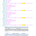
- NIC Ordering (Advanced): The vSRX will map NIC’s to each slot as it pertains to the numerical order of ‘slot’ setting as seen in ‘virsh dumpxml <id>’ command, meaning, that if you dump the virsh XML you will see configuration for “<interface type=’bridge’>” and what you have to pay attention to is the section for ‘slot=0x0#’. The lowest will be fxp, second up from there is em0, third is fabric, and fourth is your internet NIC.
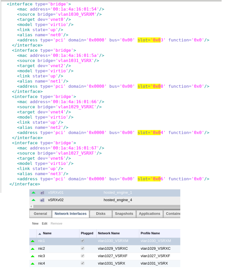
NOTE A BUG in oVirtThat while I was doing my setup it was observed the em0 control link could not see its partner. What was identified was that oVirt had shown me that the NIC order was as it was needed for a cluster in vSRX, however, when I ran 'virsh dumpxml ${ID}', where ${ID} is the ID of the VM, and looked at the order of slot= it was evident the order was not how we needed it where fxp should be lowest then em0 second, and so on. This identified that while oVirt had the order correct on the front end UI, the XML behind the scenes had the FXP bridge on slot='0x06' whereas it needed to be on slot='0x03'. The fix here was to change the vNIC network association in oVirt UIHere is an example of correct / oVirt outputting vNIC config to the XML as it shows in the UI. I highlight slot=’0x’ so you can see the part I am referencing that matters the most to the vSRX clustering component
You’ll notice that I have the NIC’s in the order they need and what I expect in the XML output. What was noticed on the vSRX cluster was that they couldnt see each other. This made it clear the em0 control links were not configured correctly in some fashion. At this point looked at the at the virsh dumpxml output for the VMs and could see that the NIC association in the XML was wrong being that vSRX expects fxp NIC to be the lowest slot= #. I no longer have that XML output but it was easy to figure out what to do since you could see the MAC address. Take that and cross it to what the oVirt UI shows and then reconfigure the network association accordingly. Here is what mine ended up coming out to be for my secondary:
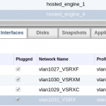
Instead of FXP, em0, fabric, ge-0/0/0 it had to become fabric, fxp, em0, ge-0/0/0
- fab0/1 MAC address generation (Clustering): This was a strange and tough one…the MAC addresses for fab0 and fab1 are generated by the vSRX on first boot. The last two bytes of these MAC addresses are borrowed from the first two bytes of the MAC for the fxp0 interface. So, what this means, is if you leave oVirt auto-generated it will end up generating the same MAC for both nodes. In a cluster you need to change the fxp0 link (vnic1) to have different first two bytes in the MAC addresses on the secondary vSRX so it will generate unique MAC addresses
- We are going to be doing this as a cluster. Some things executed in a cluster are not applicable to standalone
- oVirt doesnt make it easy to import images (at least that I tried). The easiest way I did this was to download the KVM image Juniper to one of your nodes. Create the VM with its backing storage and then use dd to overwrite it in place – more on this later
- Using the oVirt console with remote-viewer wont be helpful here. vSRX loads Windriver Linux first and then kicks off virtualization layer for the actual JunOS software. I outline how to obtain a console below
Setup
- 2 KVM nodes on CentOS 7
- oVirt 4.x
- 4 networks configured in oVirt (outside of ovirtmgmt) – this equates to a Layer 2 bridge. In my setup I had them actually VLAN tagged so the #’s there reference their VLAN tag # on my network and how it was configured in oVirt
- vlan1029_VSRXC 10.0.29.240/28 – Control link em0 (we dont actually IP this on the vSRX)
- vlan1027_VSRXF 10.0.27.240/28 – Fabric link (fab0/1)
- vlan1030_VSRXM 10.0.30.240/28 – Management link / fxp0
- vlan1031_VSRX 10.0.31.240/28 – Main untrust interface to the internet
- vSRX01 pinned to KVM node 1
- vSRX02 pinned to KVM node 2
Execution
- As outlined above, first make sure you have your VM networks setup and you have your two KVM nodes active and working in your oVirt cluster. Create two new VM’s and name them ‘vsrx01’ and ‘vsrx02’. Create the VM as you normally would with backing storage (doesnt matter the size as we blow it away anyway). Click ‘Console’ on the left in the settings dialog and configure it as video type CIRRIUS
- Now navigate here and login when prompted after clicking the KVM image. Accept the license and then copy the URL in the box
- Now SSH to KVM node 1 and use the following command:
curl -o vsrx.qcow2.img ${URL}Where ${URL} is the URL you copied from the Juniper download page
- Now we need to convert the disk from qcow2 to raw. I could not seem to get it to work with qcow2 which was odd to me. If I left it as qcow2, oVirt refused to boot it
qemu-img convert -O raw vsrx.qcow2.img vsrx.raw.img
- Now you need to locate the path to your disk – an example (up until dd command) is provided below for the steps for the shell commands
- Click the virtual machine tab in the oVirt web UI
- Left click your VM vsrx01
- Click the disk tab in the lower panel
- Note the name of your disk – it should be vsrx01_Disk1
- Now on the top tab click “Disks
- Locate your disk – then left click it
- In the lower panel observe the ID #
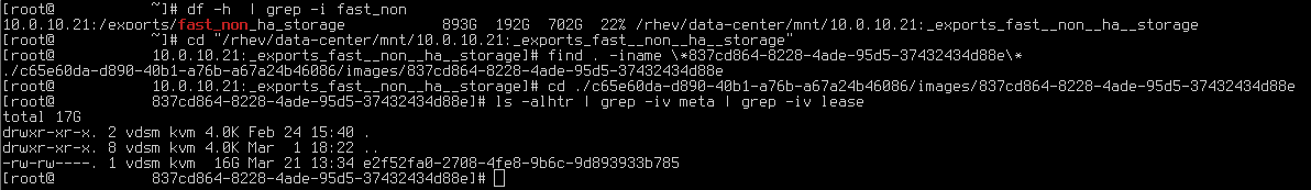
- On the KVM node you are on where you downloaded and converted the KVM image file do a ‘df -h‘ and locate the full path to the underlying storage for the volume where your disk resides. For me I know ‘DS_PROD_NON_HA_NFS_1’ resides on 10.0.10.21 as you can see below
- Now, cd to that base path (easier this way)
- Execute a find command with the switch -iname and include your disk ID – this will help you locate the full path to your disk as it pertains to your VM
find . -iname \*837cd864-8228-4ade-95d5-37432434d88e\*
- Now that you have that relative path for where you are – for me it is ‘./c65e60da-d890-40b1-a76b-a67a24b46086/images/837cd864-8228-4ade-95d5-37432434d88e’ – cd to that directory
- Now you have located your VM’s disk image. Here is where you will run dd to put the vSRX image in place
dd if=/root/vsrx.raw.img ${FILE} bs=4M status=progressWhere for me ${FILE} would be ‘e2f52fa0-2708-4fe8-9b6c-9d893933b785’
If you get an error about ‘status=progress’ then just remove that part. Fairly certain oVirt 4.x requires CentOS7/RHEL7 so you should have that flag
- Repeat this for second vSRX as well
- Below you can see a screenshot of an example of the shell commands
- Now that you have the images deployed its time to come back to the vnic configuration as outlined above –
- Go back to the ‘Virtual Machines’ tab in oVirt web UI
- Left click your VM
- Then in the lower panel click ‘Network Interfaces’
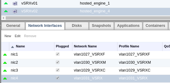
- As outlined above, configure your vNIC as such:
- vnic1 = fxp interface – vlan1030_VSRXM
- vnic2 = em0 interface – vlan1029_VSRXC
- vnic3 = fab interface – vlan1027_VSRXF
- vnic4 = ge-0/0/1 interface (ge-0/0/0 will be used for fab link)
- As you recall, on the secondary vSRX make sure to change the first 2 bytes of the MAC address for vnic1 / fxp interface. It can be anything
- Additionally, right click your VM’s and go to edit. Click ‘Custom Properties’ and type ‘macspoof’ with a value of ‘true’. This will allow the vSRX to, you guessed it, spoof MAC addresses
- Once confirmed, start your VMs
- If while doing the setup you dont get the cluster built or control links cant see each other, then please reference my note above about confirming the vNIC real ordering via the virsh xml and slot config setting
- First boot can take awhile – anywhere between 5-10 minutes – as it initiates all the interfaces. Dont bother with the usual console viewer that you are used to with most VM’s in oVirt. Rather, SSH to the KVM node for where your VM’s are running and run the following to obtain the path to the socket file containing the console access you need and can reach via nc
$ ps -Aef | grep -i charserial0 | tr ',' '\n' | grep -i 'vmconsole'
path=/var/run/ovirt-vmconsole-console/5ded6037-e0b2-4e41-8b7b-9b43e3e8a5cf.sock
Now take what you see after path= and use nc (‘yum install nc’ if you have to) to connect
$ nc -U /var/run/ovirt-vmconsole-console/5ded6037-e0b2-4e41-8b7b-9b43e3e8a5cf.sock
<press return>
secondary:node1}
root@vsrxv02>
Of course, the above example is from my live setup
Note: I cannot recall if the above comes out of the box for oVirt. I believe it does but if the above does not work for you then you need to spend a few to get vmconsole set up. I believe the above works fine and the function I describe is to access virsh console over SSH
- At this point with nc and attached to the consoles. Login with ‘root’ and do the usual stuff like setting root password and such –
Hint: If you need to ctrl+c do ctrl+v then ctrl+c and then press return- Enter cli
- Enter conf
set system root-authentication plain-text-password
- Enter the password you want to use
- Configure your fxp0.0 – for me it was for primary:
set interfaces fxp0.0 family inet address 10.0.30.241/28
And for secondary it was .242/28
- Type exit to back out of config mode and now we’re going to set the chassis cluster configuration and reboot. NOTE: When you do this you are only going to have one fxp0 so if you notice some “weirdness” after you boot back up and trying to use fxp IP for management, thats why. By weirdness I mean if you are SSH’ed in and then it drops then you SSH again and now you’re on the secondary…this is because you need to setup group configuration for fxp. I wont cover that here but you can find the KB article here
Primaryset chassis cluster cluster-id 5 node 0 reboot
Secondary
set chassis cluster cluster-id 5 node 1 reboot
- Now once you’re back and booted up you can run the following. This is straight out of juniper documentation for setting fabric link and set reth devices-
user@vsrx0# set interfaces fab0 fabric-options member-interfaces ge-0/0/0
user@vsrx0# set interfaces fab1 fabric-options member-interfaces ge-7/0/0
user@vsrx0# set chassis cluster reth-count 2
user@vsrx0# set chassis cluster redundancy-group 0 node 0 priority 100
user@vsrx0# set chassis cluster redundancy-group 0 node 1 priority 10
user@vsrx0# set chassis cluster redundancy-group 1 node 0 priority 100
user@vsrx0# set chassis cluster redundancy-group 1 node 1 priority 10
user@vsrx0# commit
- That should be it! Please reach out in the comments if you have any questions or hit any issues